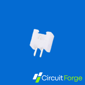
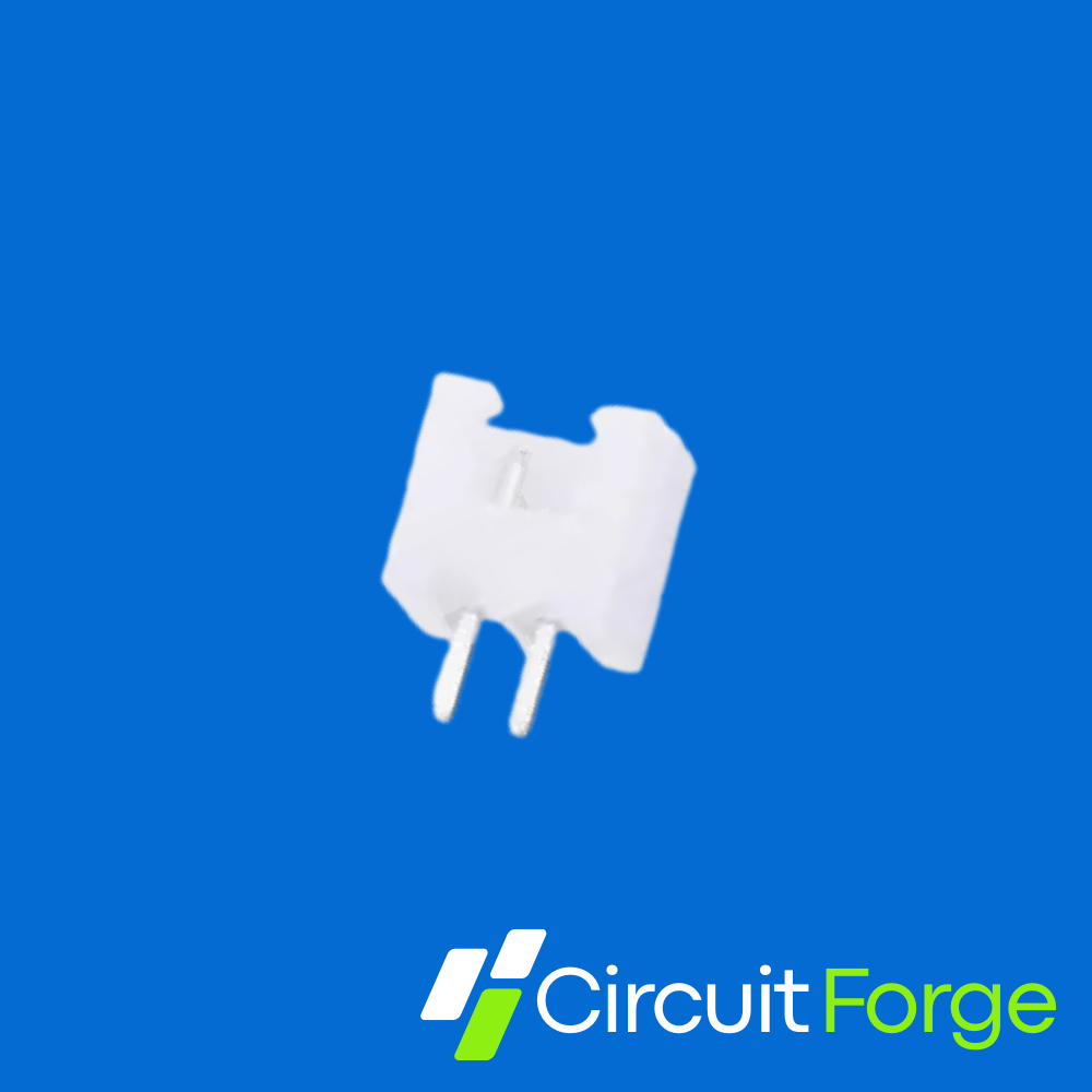

2515 Series 2-Pin Straight Male PCB Connector
A compact, shrouded two-pin male header for detachable wire-to-board connections. The straight, through-hole pins support PCB mounting, while the polarized housing guides a matching female connector into the intended orientation.
Key Features
2-Pin Connection
Single-row male header for power or signal wiring.
Straight PCB Mounting
Vertical through-hole pins for soldered PCB assembly.
Polarized Housing
Helps prevent reversed insertion of the correctly matched housing; wire polarity must still be checked.
Detachable Wiring
Useful for modular assemblies, servicing and replacing connected modules.
Product Details
| Parameter | Details |
|---|---|
| CircuitForge SKU | CF1031 |
| Listed series | 2515 |
| Positions / rows | 2 positions / 1 row |
| Contact type | Male pins |
| Orientation | Straight / vertical |
| Mounting | Through-hole PCB mount |
| Pitch | Previously listed as 2.54mm; confirm the supplied part before choosing a PCB footprint or mating housing |
| Mating connector | A matching two-position female housing with compatible contacts, pitch and keying |
Pitch and Compatibility
Check before ordering: Official JST XH connectors use 2.50mm pitch. A connector listed as 2.54mm should not be assumed to have the same footprint or guaranteed mating compatibility. Contact CircuitForge to confirm the supplied connector dimensions and matching housing.
The official JST XH reference lists 3A AC/DC with AWG 22 wire, 250V AC/DC and an operating temperature range of −25°C to +85°C, including current-related temperature rise. These reference values apply to the specified JST parts and mating system; they do not independently certify the stocked 2515 connector.
Typical Applications
- Detachable sensor and module connections
- Low-voltage power wiring, within the confirmed connector rating
- Embedded electronics and small control boards
- Robotics and automation modules
- LED and consumer-electronics assemblies
PCB and Assembly Guidance
- Confirm pin pitch, hole size, housing outline and mating orientation before releasing a PCB footprint.
- Mark polarity and pin numbers clearly on the PCB silkscreen.
- Check wire polarity even when using a polarized connector.
- Choose PCB copper width using current, copper thickness, temperature-rise target and trace location; a single fixed trace width is not suitable for every design.
- Select compatible female housings and crimp terminals; do not assume universal JST-XH or breadboard compatibility.
- Provide adequate solder joints and wire strain relief.